


")


Hardware Required
- Arduino or Genuino Board
- LED
- 220 ohm resistor
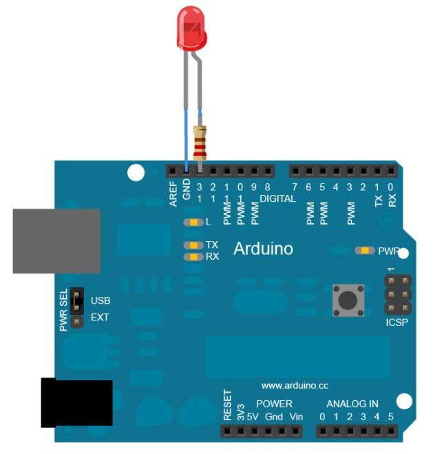
Circuit
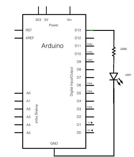
To build the circuit, connect one end of the resistor to Arduino pin 13. Connect the long leg of the LED (the positive leg, called the anode) to the other end of the resistor. Connect the short leg of the LED (the negative leg, called the cathode) to the Arduino GND, as shown in the diagram and the schematic below.
Most Arduino boards already have an LED attached to pin 13 on the board itself. If you run this example with no hardware attached, you should see that LED blink.
The value of the resistor in series with the LED may be of a different value than 220 ohm; the LED will lit up also with values up to 1K ohm.
Schematic
Code
After you build the circuit plug your Arduino or Genuino board into your computer, start the Arduino Software (IDE) and enter the code below. You may also load it from the menu File/Examples/01.Basics/Blink . The first thing you do is to initialize pin 13 as an output pin with the line
pinMode(13, OUTPUT);
In the main loop, you turn the LED on with the line:
digitalWrite(13, HIGH);
This supplies 5 volts to pin 13. That creates a voltage difference across the pins of the LED, and lights it up. Then you turn it off with the line:
digitalWrite(13, LOW);
That takes pin 13 back to 0 volts, and turns the LED off. In between the on and the off, you want enough time for a person to see the change, so the delay() commands tell the board to do nothing for 1000 milliseconds, or one second. When you use the delay() command, nothing else happens for that amount of time. Once you've understood the basic examples, check out the BlinkWithout Delay example to learn how to create a delay while doing other things.
/*
Blink
Turns on an LED on for one second, then off for one second, repeatedly.
Most Arduinos have an on-board LED you can control. On the Uno and
Leonardo, it is attached to digital pin 13. If you're unsure what
pin the on-board LED is connected to on your Arduino mode
*/
// the setup function runs once when you press reset or power the board
void setup() {
// initialize digital pin 13 as an output.
pinMode(13, OUTPUT);
}
// the loop function runs over and over again forever
void loop() {
digitalWrite(13, HIGH); // turn the LED on (HIGH is the voltage level)
delay(1000); // wait for a second
digitalWrite(13, LOW); // turn the LED off by making the voltage LOW
delay(1000); // wait for a second
}

1 Comment(s)
Thank you for the suggestion. I\'ll give it a try.
Leave a Comment